Where catalog equipment fails
Pneumatic conveying, classification, grinding and fluidized beds for abrasive, sticky and dusty materials. We design, build and commission turnkey.
- turnkey soda ash system
- 1,200t/day
- soda ash line, railcars to production
- ~300m
- lower classification limit
- 5µm
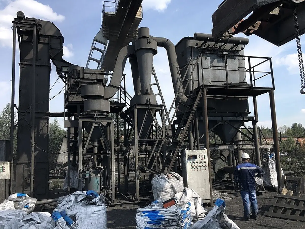
Grinding and classification unit at a client site
We work where the material sticks, wears the pipe, dusts or cakes.
| Industry | What fails | What we install | In numbers |
|---|---|---|---|
| Chemicals | Abrasive and aggressive powders: chromium oxide, alumina. Dusty powders: soda ash. | Blow tanks with internals designed for the specific material. | 1,200t/dayturnkey soda ash system |
| Mining | Screws become the bottleneck as throughput grows. | Pneumatic conveying of backfill instead of screw conveyors, without expanding the site. | 47→70+m³/hbackfill feed |
| Fertilizers | Product cakes and granules break during transport. | Granulation, fluidized bed cooling, drying, low-velocity conveying. | 12.5t/hfluidized bed cooler |
| Metallurgy and waste | Slag and dust go to the dump. | Air classification from 5 µm to 5 mm: slag becomes a saleable abrasive. | 83%coarse product yield from slag |
| Cement and lime | Screws and conveyors wear out and dust when feeding silos. | Low-velocity pneumatic conveying: a closed line with baghouse filters and a blow tank built for your material. |
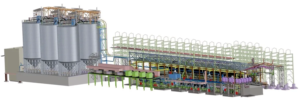
Soda ash, 1,200 t per day: from railcars to production through 300 m of pipe
Soda ash (sodium carbonate)
- ~300mtotal distance
- 42mvertical lift
- 4barair pressure
- 1,200t/daycapacity
- Challenge
- A chemical plant receives soda ash in hopper cars, 1,200 t per day. It has to be unloaded at 8 stations, lifted 42 m and delivered to storage and to production at the operating plant, without dusting or product loss.
- What we did
- Process technology, design, equipment and commissioning. Two stages: railcars → storage, storage → production. The blow tank and the vibratory railcar unloading are our own design; the blow tank was built for soda ash. Baghouse filters in every area.
- Result
- The system has been commissioned at an operating plant: 60-80 t/h per blow tank, closed line, baghouse filters in every area. A system of the same type runs in another area of the same plant.
These are soda ash numbers. For your material, the test shows the numbers.
System components
| Unit | Specification |
|---|---|
| Railcar unloading blow tanks | 8 units, 7 m³, 60-80 t/h, DN250, 150-200 m line |
| Production feed blow tanks | 2 m³, 15-30 t/h, DN250, 50-150 m line |
| Storage silos | 2,500 m³ |
| Production day bins | 200 m³ |
| Baghouse filters | 50 m², 5,400 m³/h |
| Compressor stations | 90 Nm³/min, 0.7 MPa |
Client: a large chemical plant that consumes soda ash.
Case studies
Figures from industrial installations delivered by our engineering team, which has worked together since 2017. We do not disclose client names; details on a call.
Mine: backfill feed up 49% without expanding the site
Screws were the bottleneck. We replaced them with low-velocity pneumatic conveying.
- backfill feed
- 47→70+m³/h
Slag turned into product: abrasive powder instead of waste
A 50 t/h air classifier that turns slag into abrasive powder. Results published in a scientific paper.
- classifier
- 50t/h
- coarse product yield
- 83%
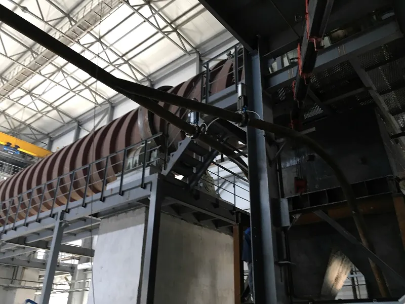
Sulfur fertilizers: a line from liquid sulfur to dry granules
Liquid sulfur granulator, fluidized bed cooler, rotary dryers, heated baghouse. Central Asia.
- baghouse filter
- 600m²
How we work
First the numbers for your material, then the commercial proposal.
Problem review
30-minute video call with an engineer: material, capacity, what fails today.
- Outcome
- test success criteria, in writing
Sample test
We test the sample on a laboratory unit; the quantity is agreed in advance. We sign an NDA before you ship the sample.
- Outcome
- test report with the agreed numbers
Proposal and design
A proposal based on the test numbers. After the contract: process design, line sizing, documentation.
- Outcome
- a design that fits your operating plant
Fabrication
Blow tanks, classifiers and filters of our own design.
- Outcome
- equipment sized for your material
Installation and start-up
Installation supervision, commissioning, staff training.
- Outcome
- a system running at design capacity
Fabrication and engineering
Our engineers design and test, equipment is built at the shop chosen for each project, our representative in Brazil runs the project on site.
- Own designs
- Blow tanks, air classifiers, jet mills.
- Built to order
- We choose the fabrication site to suit the project and client requirements.
- Testing
- Laboratory units for pneumatic conveying and classification. We test samples together with a university research group: our classifier design model matched a 50 t/h industrial unit.
- classification range
- 5 µm - 5 mm
- per blow tank, on soda ash
- 60-80 t/h
- air consumption
- 40-80 Nm³/t
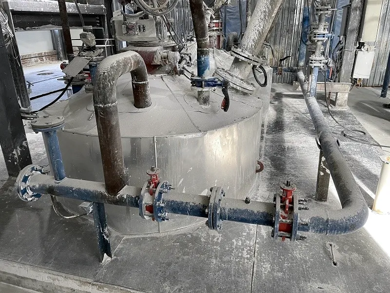
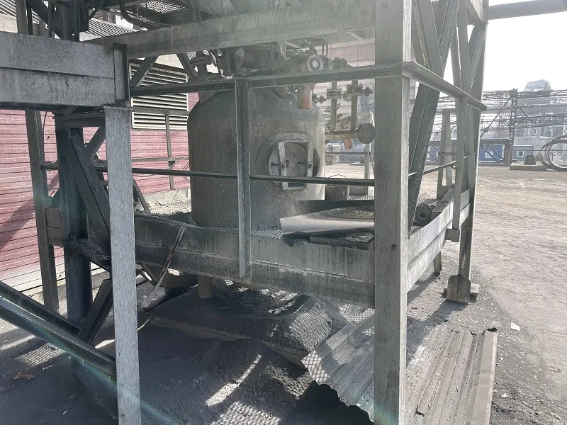
Blow tank with piping at a plant 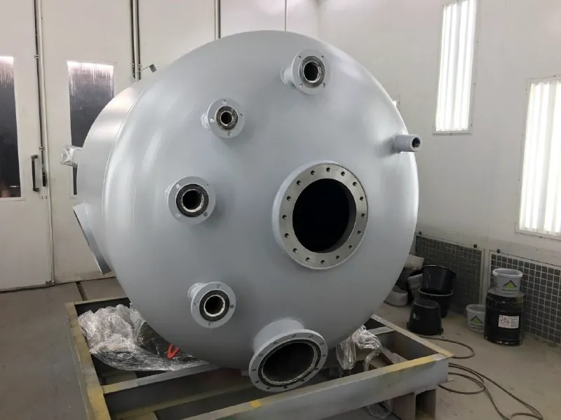
Flanged vessel in the paint booth 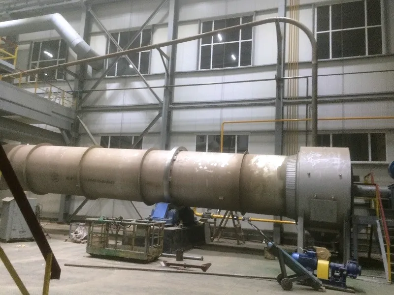
Rotary drum in the shop 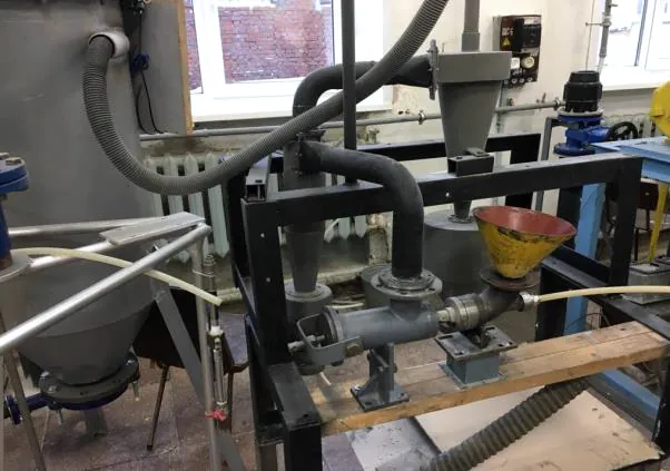
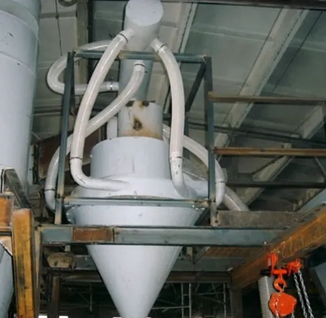
Laboratory pneumatic conveying rig for sample tests
Tell us about your process
Message us on WhatsApp or fill in the form. We review the problem and suggest a time for a call.
We reply within one business day, Brazil time.
Useful for the call
- material name and data sheet, if available
- line capacity, t/h
- photos of the problem point